PCB Milling with Modela

Machine: Modela MDX 20
Software: Mods
When you are working with electronics, you can make prototypes with Arduino. However, when you want to embed a programmed microchip in a design you need to design the PCB (Printed Circuit Board) itself to mount.
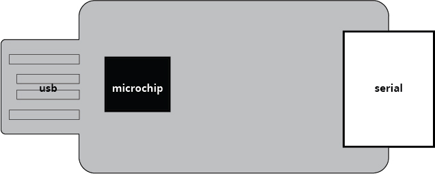
For this tutorial, we made our own UART (universal asynchronous receiver-transmitter). computer hardware device for asynchronous serial communication in which the data format and transmission speeds are configurable. The UART interface consists of two pins: the Rx and Tx pin. The Rx pin is used to receive data. The Tx pin is used to transmit data. When two devices are connected using a UART, the Rx pin of one device is connected to the Tx pin of the second device.
Modela bed is made of 4 layers.

Always measure the thickness of the copper plate at several locations and use the thickest measurement.
Clean the sacrificial layer with sticker remover. Fully cover the surface where the copper plate will be placed with double-sided tape but avoid overlaps. Place the copper plate and press firmly on the plate with a or paper towel (avoid touching too much with hands).
Useful things to know!
There are two types of copper plates:
- One-sided copper plate: used for surface mount devices (SMD) - this tutorial uses a one-sided copper plate.
- Double-sided copper plate: used for through-hole devices.
Milling bits:
- 0,8 mm thickness: used to make edge cuts
- 0,4 mm thickness: used to make interiors
Flutes on the milling bits:
- 1 flute: Standard (cuts faster; eats away more material at a time) - this tutorial uses a 1-flute milling bit.
- 2 flute: more precise (cuts slower)
We firstly cut the interiors and then the edge cuts.
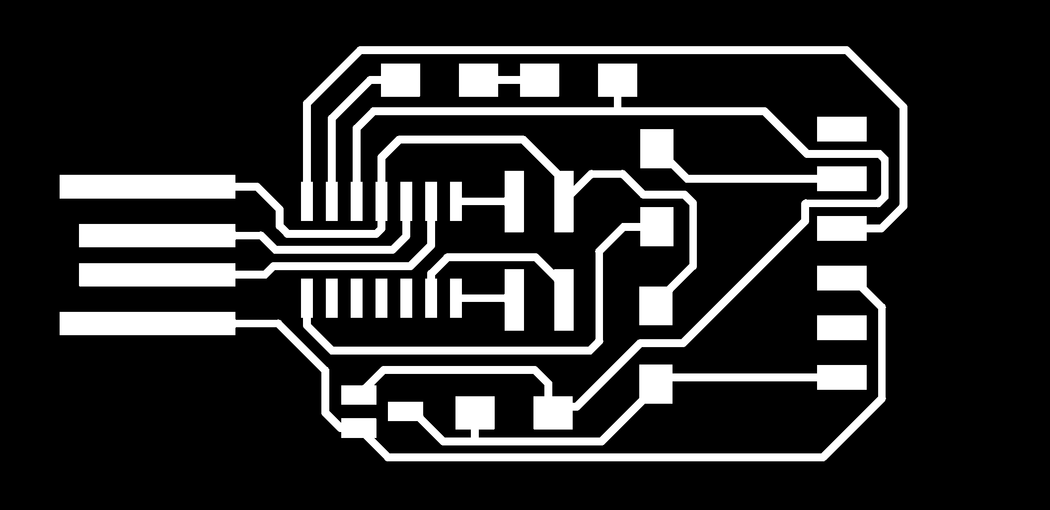
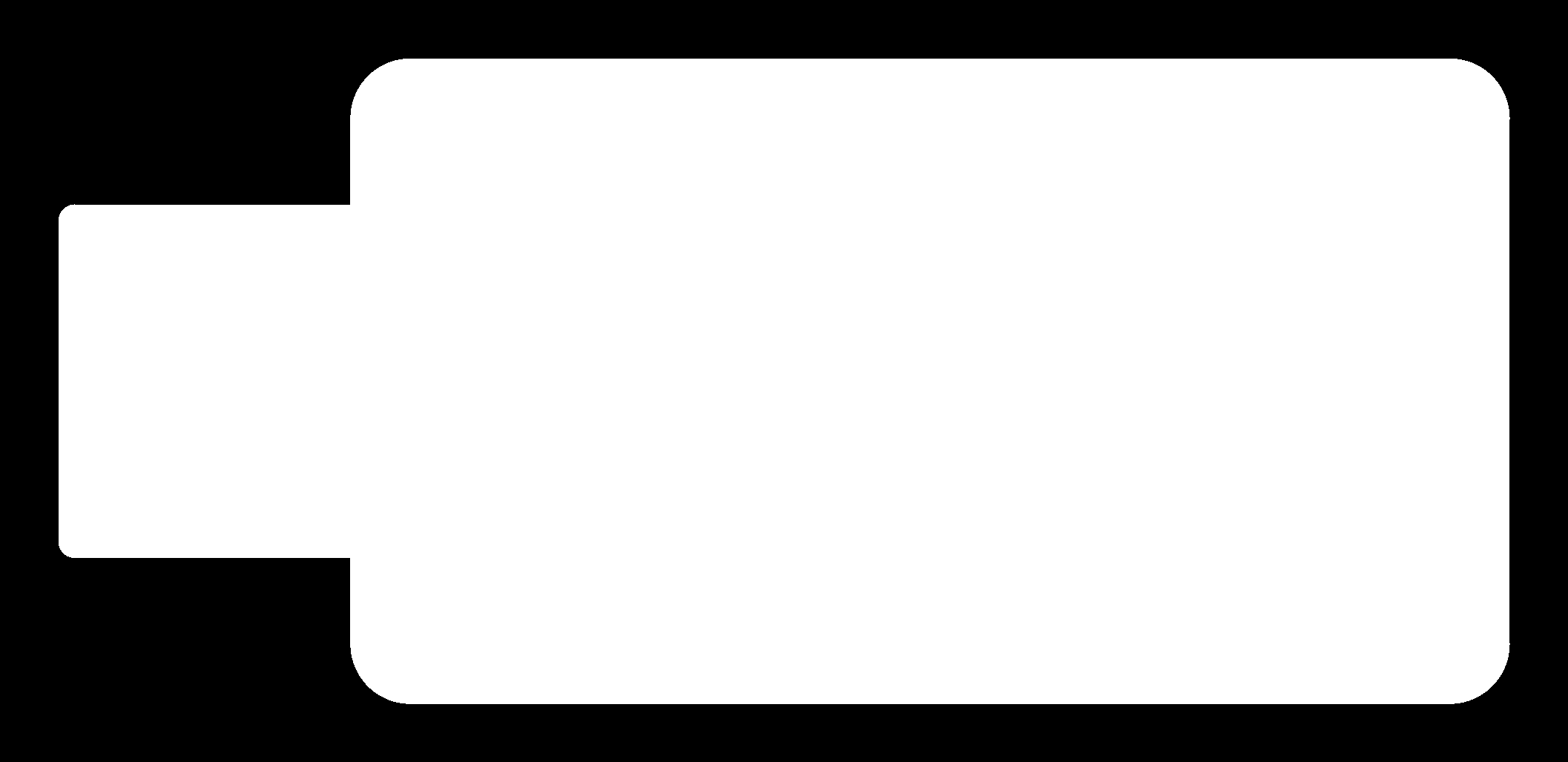
The design image should have a DPI value of 1000. If it is not the case, you can change this value in Mods later on. In the design image:
- White color: Parts you want to keep
- Black color: Parts you want to remove
The files we will use in this tutorial are as follows, first two are interiors and the third is edge cut:

Turn ON the machine and make sure it is not in VIEW mode.

Open the terminal on the computer the machine is attached to. Go to terminal and type:
mods- Cancel the authentication twice
This prompts an explorer page to open with Mods entry. Follow the steps down below to start the machine interface.

In the Mods screen, follow the steps below to mill your design.


When the milling is finished Press VIEW on the Operation Board and check everything is good. Once all the milling is done, remove the milled part with a scraper and wash it with soap.
