PCB Assembly
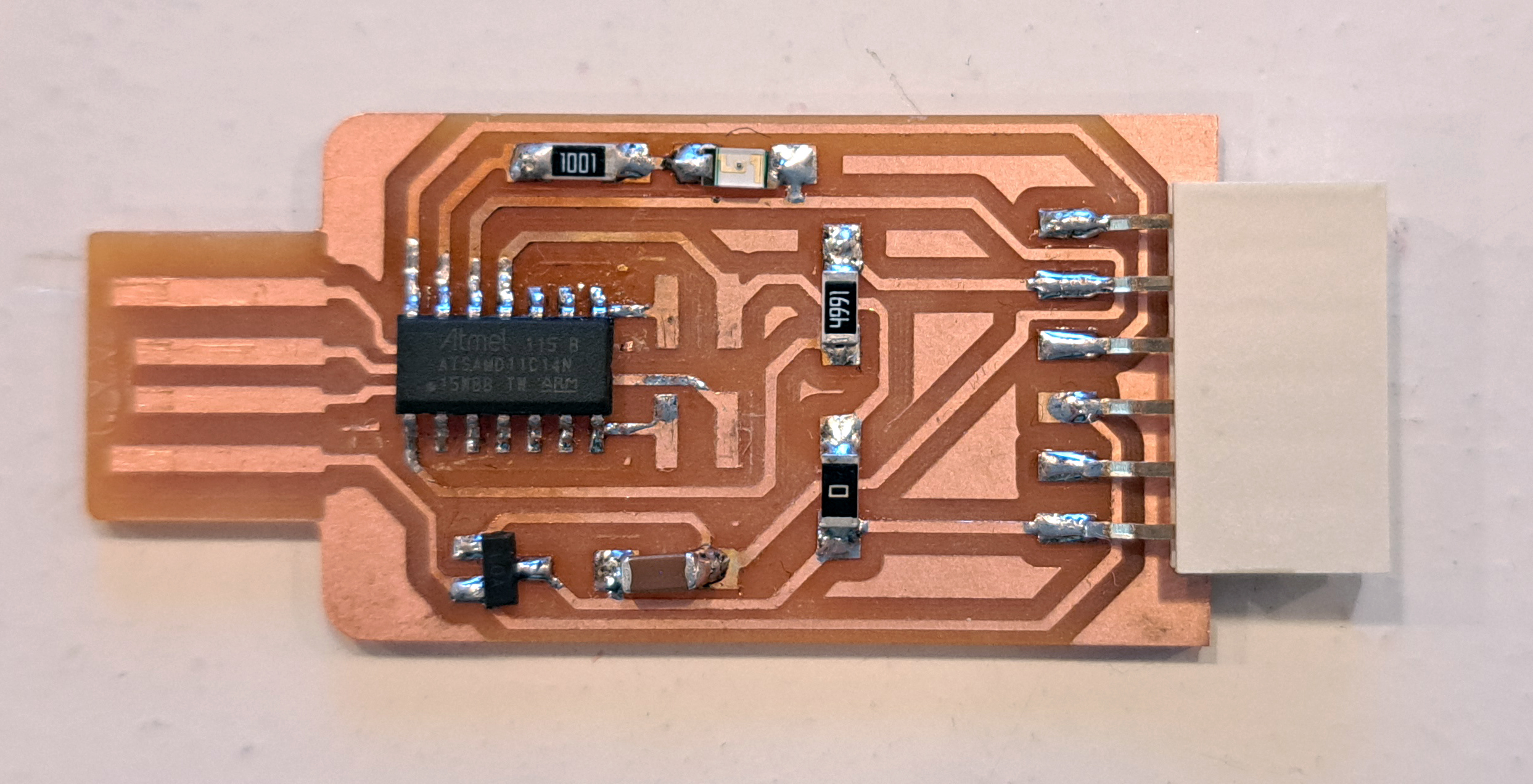
We milled a UART board previously. In this tutorial, we are soldering the board.
There are two types of boards:
- SMD (surface-mount device) boards
- Through-hole boards
SMD components are smaller and the process of soldering is slightly different than through-hole soldering.
The UART board falls into the category of SMD boards.
We used the board schematics and BOM (Bill of Materials) from the following website: http://pub.fabcloud.io/programmers/programmer-serial-d11c/ibom/
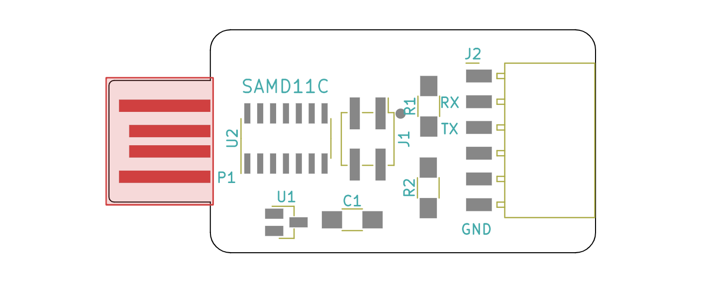
The design above does not include the LED light and its resistor. Therefore, the following is the actual material list:
| Ref | Value | Footprint | Qty |
|---|---|---|---|
| C1 | 1uF | C_1206 | 1 |
| R1 | 4.99k | R_1206 | 1 |
| R2 | 0 | R_1206 | 1 |
| U1 | Regulator_Linear_LM3480-3.3V-100mA | SOT-23 | 1 |
| U2 | SAMD11C | SOIC-14_3.9x8.7mm_P1.27mm | 1 |
| J1 | Conn_PinHeader_2x02_SWD_P2.54mm_Vertical_SMD | PinHeader_2x02_SWD_P2.54mm_Vertical_SMD | 1 |
| J2 | Conn_Socket_FTDI_1x06_P2.54mm_Horizontal_SMD | Socket_FTDI_01x06_P2.54mm_Horizontal_SMD | 1 |
| P1 | Conn_USB_A_Plain | Conn_USB_A_Plain | 1 |
| 1k | R_1206 | 1 | |
| LED light | 1 |
Apart from the board and the components, you need these materials for soldering:
- Solder iron
- Solder iron stand
- Solder
- Multimeter
- Magnifying glass
- Diagonal cutter pliers
- Tweezers
- Solder wick braid (to remove solder from unwanted places)
- Brass wool (to clean the solder iron tip)
- Damp sponge (to clean the solderiron tip)
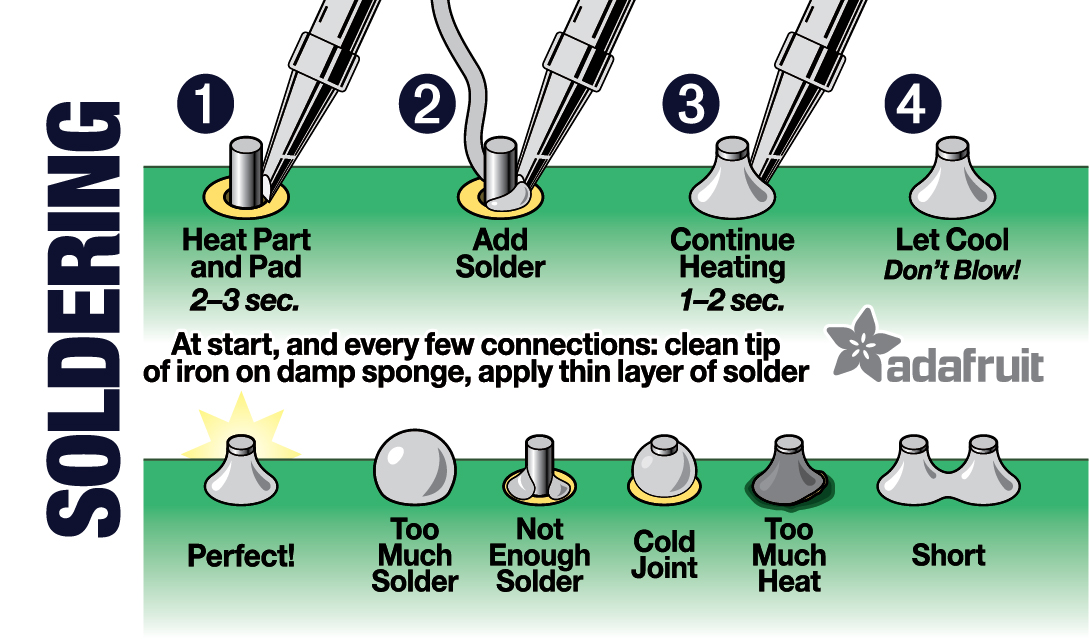
I have found helpful step-by-step soldering howtos from Adafruit.
-
https://blog.adafruit.com/2016/12/26/new-reference-card-soldering-101/
-
https://learn.adafruit.com/adafruit-guide-excellent-soldering